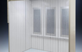
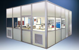
Cleanrooms have become the norm in nanotechnology, biotechnology, biomedical research, microelectronics fabrication, and other fields that are highly sensitive to environmental contaminants such as airborne microbes, dust, aerosol particles, and chemical vapors. In many cases, environmental dynamics such as sound pressures and structural vibrations are of equal concern. Cleanrooms have traditionally been designed as enclosed environments with a specified number of particles per cubic meter at a defined particle size. This article addresses some of today’s solutions for vibration control in cleanrooms where micro-vibration-sensitive equipment (MVSE) is used.
Vibration sources
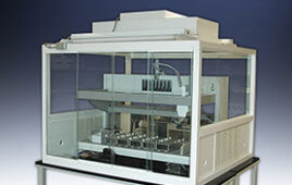
Sound pressures, vibration amplitudes, and temperature changes can impart major impacts on the functionality and image definition of very high-resolution equipment such as laser-based interferometers, scanning probe microscopes, scanning electron microscopes (SEM), transmission electron microscopes (TEM), and photolithography. Vibration concerns in cleanrooms are much more common today due to three factors: 1) advances in technology resulting in higher resolution optical equipment; 2) the abundance of labs installed on upper floors; and 3) the structural designs of the buildings tending towards lighter weight construction. The key element in lab vibration control is the slab or supporting structures under the MVSE. Though slabs on grade are preferred for MVSE labs, the sheer number of new labs today has exhausted this option and upper level installations are now the most common.
Intruding vibrations can be grouped into local and external sources. Local vibration sources are generally mitigated at the source when possible, while external occurrences are attenuated somewhere along the transmission paths.
Local sources such as exhaust hoods, fans, motors, pumps, air handling units, vertical transport, and footfall in adjacent areas are among the many sources of vibrations that travel through building structures. In the actual lab, both walking and conversation have been known to be problematic on occasion. Essentially, when an upper level slab or supporting structure vibrates, the MVSE is susceptible to horizontal motions as well as vertical movement.
Vibrations from external sources such as nearby construction, adjacent road traffic, delivery loading docks, and rail lines transmit vibrations via soil strata into buildings. Sound from aircraft, wind loads, and other weather conditions can create structural movements in facades and roofs translating into building motions. Building footprints can offer a stabilizing effect that can mitigate upper level transitional or torsional motions due to wind shear and groundborne vibrations. Smaller or narrow footprints will cause greater horizontal motions.
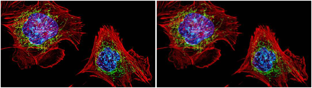
The cells shown here are fibroblasts, one of the most common cells in mammalian connective tissue. These particular cells were taken from a mouse embryo. Scientists used them to test the power of a new microscopy technique that offers vivid views of the inside of a cell. The DNA within the nucleus (blue), mitochondria (green) and actin filaments in the cellular skeleton (red) are clearly visible. Simulated distortions on the right photo provide a glimpse of the effect of a vibration exceedance over threshold. Image: Dylan Burnette and Jennifer Lippincott-Schwartz, Eunice Kennedy Shriver, National Institute of Child Health and Human Development (NICHD), National Institutes of Health
Vibration criteria curves for sensitive equipment Generic Vibration Criteria (VC) developed since the 1980s are applied in three directions (vertical and two horizontal axis). Amplitudes are given as peak velocity per frequency, or third-octave band RMS spectra. The curves labeled VC-A through VC-G in Table 1 have been the standard until recently when VC-H to VC-M were introduced for evaluation purposes.
Peak values per frequency from below 1 Hz to 80 Hz are common for micro-vibration measurements. The third-octave band smoothing and RMS averaging reduce the magnitude of peak values, so care should be given when referring to data treated this way. All data should have complete indications of the metric used and any filtering applied. Whether amplitudes are presented as velocity in μin/s or μm/s, or as acceleration in g (gravity), μin/s², or μm/s² will depend on the project, client, and purpose. Ground-borne vibrations are generally measured at or below the ground surface. The measured unit magnitudes are reported as peak particle velocity (PPV) in in/s, or mm/s. Building vibrations are measured with tri-axial accelerometers anchored directly to building structures such as façade masonry, foundations, or structural columns. The measured unit magnitude provided by accelerometers is acceleration in g where 1 g=9.08665 m/s² or 386.1 in/s².
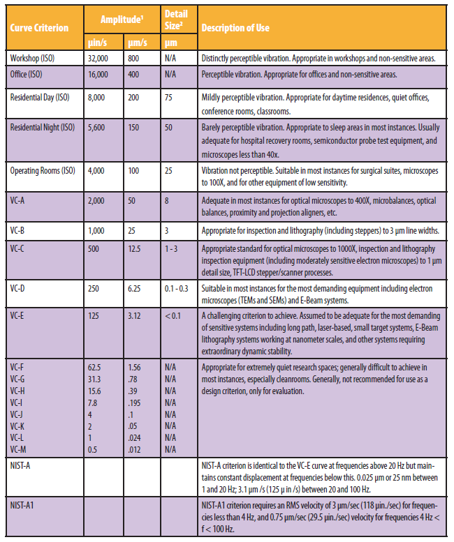
1. As measured in one-third octave bands of frequency over the frequency range 8 to 80 Hz (VC-A and VC-B) or 1 to 80 Hz (VC-C through VC-G). 2. The detail size refers to line width in the case of microelectronics fabrication, the particle (cell) size in the case of medical and pharmaceutical research, etc. It is not relevant to imaging associated with probe technologies, AFMs, and nanotechnology.
Design considerations
Localization of buildings away from known exterior noise and vibration is possibly the most effective first step. Increasing the weight of the building shell or core can influence the reaction to ground-borne vibrations in a positive way. Increasing the floor slab/column stiffness of each level with MVSE labs is also a common strategy.
Locally, under each MVSE unit, vibration isolation strategies can combine passive and active technologies to achieve the criteria recommended by the manufacturer. In these cases, the actual detailing of the vibration isolation design should be included in the construction drawing set. These details will help ensure that the practicality and vibration transmissibility targets will function coherently with the cleanroom criterion.
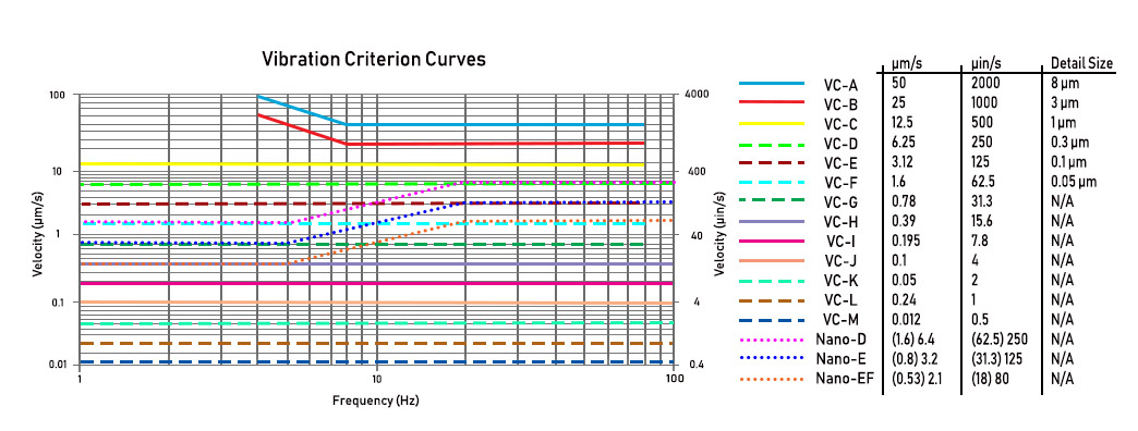
A visual representation of the given Vibration Criterion. Image: Metropolitan Acoustics
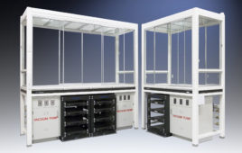
Vibration isolation tables and workstations can satisfy cleanroom and contamination standards for smaller, lighter equipment. Local equipment isolation such as air tables provide isolation primarily in the vertical direction, but they have limited horizontal isolation capability. Air table systems amplify vibrations in the range of 1.5 Hz to 3 Hz due to the natural frequencies at which air tables resonate. There are several techniques that reduce these resonant peaks, but the best design is when concerns like this have been anticipated and all limitations have been addressed.
Floating slabs can be recessed into the base building slab and aligned to finish flooring. The complexity of floating slabs installed on upper levels is by far easier during the design phases than after the building is complete. In some cases, isolation cabins with vented exhaust systems in compliance with cleanroom standards completely enclose the MVSE. Accessibility to all functions, from all directions, should be considered.
Cleanrooms have stringent criteria that arewidely recognized. Due to the speed with which technologies develop today, the importance of identifying complete vibration criteria for each ultrahigh vibration-sensitive device during early design phases is vital to the successful outcome of the project and budget.
As the president and founder of Metropolitan Acoustics, Felicia Doggett brings over 28 years of experience to the firm. Felicia’s expertise in architectural acoustics and vibration monitoring continues to be an invaluable resource to her clients.
Sooch San Souci is Senior Consultant with Metropolitan Acoustics. Sooch brings over 30 years in the fields of acoustics and vibration. At Metropolitan Acoustics, Sooch heads the vibration monitoring and diagnostics department developing proprietary software and ultra-low noise hardware allowing for monitoring in real time. [email protected]; www.metro-acoustics.com