No characteristic of MEMS devices sets them apart from integrated circuits (ICs) more clearly than their sensitivity to surface contamination. An IC wafer leaves the foundry passivated for normal environmental exposure; a MEMS wafer does not. As a result, standard back-end processing steps (dicing, pick and place, die attach, wire bonding/bumping, and packaging) commonly used for ICs cannot be used for MEMS.
MEMS require special handling at every step, and typically require special packaging. Despite these special precautions, contamination effects cause yield loss throughout the backend. Special handling, special packaging, and yield loss combine to dominate the cost of MEMS devices. When this is lumped together under “packaging,” it is common for packaging to account for 80% or more of the cost of a MEMS device. This has been a key roadblock to the growth of MEMS markets.
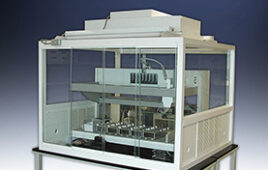
New technologies, including a bonding process developed by Ziptronix, have changed this by providing room temperature, wafer scale, hermetic encapsulation to protect the MEMS wafer before surface contamination from back-end processing can occur. An encapsulated wafer is shown in Photo 1. The application shown is for an optical device; thus the cavities can be seen through the transparent cover.


A Multidimensional Problem
Given the huge range of MEMS applications (accelerometers, RF switches, optical mirror arrays, etc.) contamination covers a range of issues. Consider an RF switch (Photo 2); when open, the contacts are 300 nm apart. Any particle lodged in this space will obviously be a problem. In addition, to achieve long-term reliability, leading manufacturers such as Radiant Technologies use proprietary coatings on the contacts. Chemical contamination of these surfaces can alter the electrical characteristics of the switch and shorten service life. Water vapor or other species with high surface tension can cause stiction effects.
For reliability, the device must be isolated in a hermetic package. When the device is isolated is a key question. Often the damage is done before packaging. Also, while hermeticity specifications are defined in terms of leakage in and out of a “sealed” cavity, the issue is more complex. A robust contamination solution must also stop permeation, which occurs when contaminants diffuse through the seal over time and outgassing where materials internal to the hermetic cavity (such as polymers or epoxies) release trace quantities of gases or vapors which contaminate active surfaces of the device.
The approach addresses all four issues:
* Direct contamination. The active device is placed in a hermetic cavity at wafer scale as an integral part of the MEMS foundry flow before any post foundry operations occur. Hermeticity is established at the earliest possible step of the manufacturing process.
*Leakage. The leakage standard set by the MIL STD 883E fine leak testing protocol is surpassed.
*Permeation. No materials such as polymers or epoxies known to allow long-term permeation are used. In fact, typically, no new materials are added. The cap used is normally a combination of Si and SiO2. It is applied to the MEMS wafer without adhesives or other bonding materials. Covalent bonding between prepared surfaces of conventional semiconductor process materials occurs without applied pressure, temperature, or electric field. Prepared materials are aligned and simply bond on contact. The menu of bondable materials is large and includes materials common to IC and MEMS processing, such as Si, SiO2, and Si3N4.
*Outgassing: Because the process takes place at wafer scale, the cavity formed can be arranged to include only the active MEMS device. Other materials used for die attach, bump preparation, or packaging are not included in the hermetic cavity. This is a large change from what is conventional today when all of these materials are in the package. With this approach, materials known to create outgassing effects are simply excluded from the hermetic cavity.
Implications
*Device design. MEMS designers have had to live with contamination effects. For example, trace surface contamination by water vapor can cause MEMS devices to stick. This sticking is often overcome by making the MEMS “return spring” stiffer. This, however, leads to excessive voltage requirements for actuation. Thus, while high performance ICs operate at less than 1.5 volts, MEMS operate at much higher voltages, often in excess of 10 volts. These voltages create a basic system incompatibility, especially for battery-powered products. Effective contamination control will enable more aggressive designs without sacrificing yield or reliability.
*Device integration.ýIntegration remains the dominant trend in electronics, and MEMS devices remain largely unintegrated. By creating MEMS die that can be handled conventionally, the increased use of MEMS in systems-in-a-package (SIP) and other advanced integration strategies can be expected.
*Cost. The largest payoff from this technology is cost. It is not uncommon for the back end of the MEMS product flow to represent 80% or more of the total cost. Special handling to avoid yield loss caused by contamination and special packaging to avoid contamination in use are the cost drivers. In many cases, this technology creates a die that can be handled and packaged conventionally, with contamination effects and yield loss equivalent to that of conventional ICs.
*Applications. The technology is based on conventional foundry tools, conventional IC and MEMS materials, and chemicals in use in foundries today. The process occurs at room temperature without applied pressure or electric field. Standard tooling allows the process to be used at any wafer scale desired. These characteristics allow applications across a huge range of MEMS devices such as accelerometers, RF switches, mirror arrays, and related devices such as surface acoustic wafer (SAW) filters.