Cleanrooms are a vital part of laboratories and the microelectronics industry, especially semiconductor manufacturing. To maintain and assure quality, there are specific standards that apply to these spaces and guide the process of constructing and operating the rooms. While adhering to these requirements makes designing and constructing a cleanroom more complex than conventional construction projects, the standards serve as a blueprint for the successful completion of a cleanroom that will meet the exacting demands of the end-user.
The need for an international standard that covered cleanroom environmental parameters and practices emerged after various countries developed their own standards, creating confusion. The International Standards Organization devised ISO 144641, which defines a cleanroom as “A room in which the concentration of airborne particles is controlled and which contains one or more clean zones.” The standard also calls for constructing the space in a manner that minimizes the introduction of particles and to control additional parameters such as temperature, humidity and pressure within the cleanroom as necessary.
Cleanroom classifications are based on the number of particles equal to and greater than 0.5 per micron (µm) in one cubic foot of air. The standard of cleanliness required is dependent on the task performed in the room, so the more susceptible the product is to contamination, the higher the standard. The standard also determines the type and frequency of testing, such as for particle count, air pressure, and air flow, required to be in compliance. Finally, the cleanroom design must account for the equipment and finishes used because each contributes to the amount of particulate in the space.
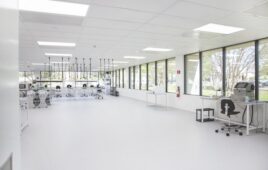
An ISO 8/Class 100,000 cleanroom, measuring 1,100 sf, completed by C1S Group for a medical device manufacturer.
The essential characteristic of a cleanroom is that it is a building within a building. These controlled environments have completely separate systems for heating, ventilation and air conditioning (HVAC), lighting, flooring, and walls. They do not share any exterior walls with the main building and do not have direct outside access. The cleanroom also has a differential pressure to the interior of the building that must be maintained at all times in order to mitigate infiltration of particles from an adjacent, less clean space into the cleanroom.
The first step in the cleanroom design process involves creating the Utility Matrix (UM), which outlines detailed specifications on each piece of equipment used in the cleanroom. This document, which is crucial to the cleanroom design, must be created and approved with the participation of the cleanroom operator/user. The UM can be developed directly by the operator, if the expertise exists in-house, or an outside consultant can be brought in to assist in development of the cleanroom layout and process flow. Once it’s completed, designers will use the UM to design the specific support systems required for the cleanroom. The UM remains an important document even after facility construction and should be continually updated throughout the life of the cleanroom.
HVAC and make-up air
The UM provides the basis for designing the HVAC/mechanical system, which is the largest component of the construction cost of a standard cleanroom facility, constituting as much as 25 percent of the total facility cost. These systems consist of recirculation air, chilled and hot water, process exhaust and makeup air systems. Although the exhaust system represents a smaller portion of the HVAC cost, it is arguably the most critical to the operational success of a cleanroom. Determining the proper amounts of exhaust for each cleanroom and support area drives the design of the make-up air (MUA) systems. The exhaust quantities are determined by careful analysis of the room, codes, and emergency requirements. By definition, the exhaust system in a hazardous production material (HPM) facility must be designed and installed to remove any potentially hazardous fumes that may escape from fabrication or support equipment.
A review of the Exhaust System Impact reveals the critical nature of starting the design process with the correct exhaust quantities. The exhaust flow rates are given in the UM and the MUA quantities are determined to cover the air exhausted from the building plus surplus air to pressurize the cleanroom (MUA=EXH+10%). MUA requirements dictate the amount of chilled water and heating water required from the central plant, thus affecting the overall size and number of chillers and boilers. Exhaust air quantity also has impact on heat removal from the cleanroom, thus affecting the size of the sensible cooling coils and recirculation air system.
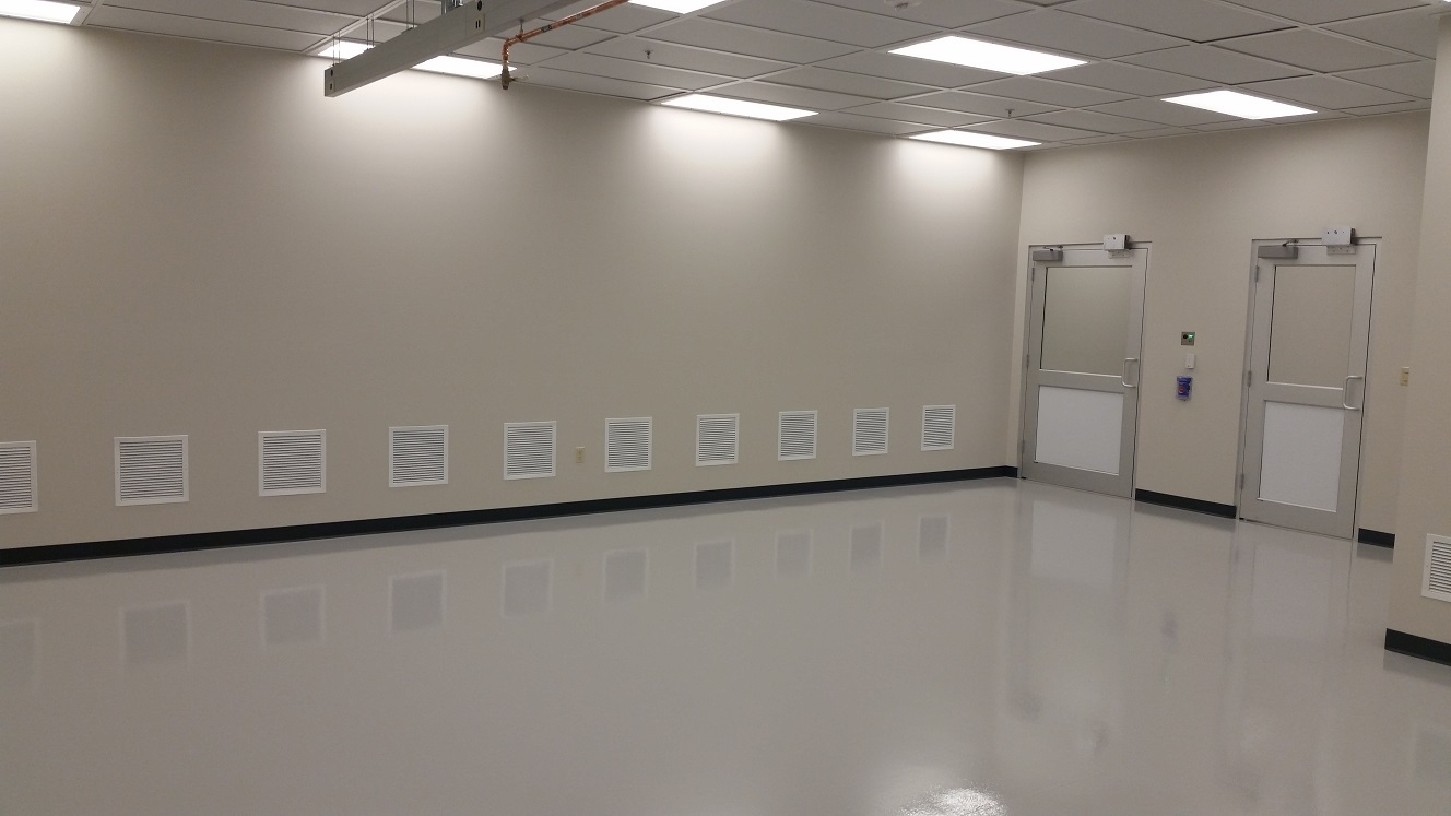
The MUA system is integral to successful cleanroom design because it not only replaces the air that is exhausted from equipment, clean spaces, and support rooms, but is also responsible for controlling the humidity levels throughout the clean spaces. Most importantly, the MUA system maintains pressure control throughout the facility. The clean spaces will typically be positively pressurized with respect to surrounding areas while the gas and chemical rooms will have negative pressure with respect to surrounding spaces. Clean areas will also see a pressure cascade going from highest pressure in the cleanest zones. This means the highest level cleanroom will have the highest pressure while an adjacent cleanroom with a lower classification will have lower pressure, the attached gowning room will have still lower pressure, and the non-cleanroom space will have the least pressure. See Table 1 for an example of a pressure cascade.
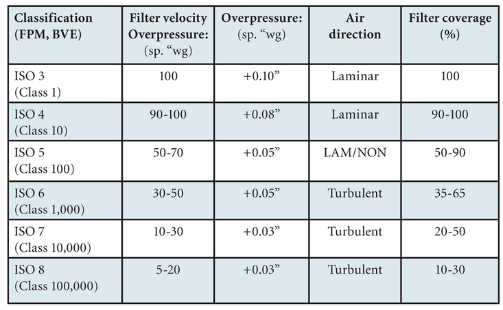
Table 1: Example cleanroom pressure cascade
Recirculation air system
The cleanroom recirculation air system is a major part of the HVAC cost for a cleanroom and must be designed to provide sufficient clean and conditioned air to the space in order to maintain the cleanroom classification during full operation of the room (see Table 2). The ceiling filter coverage and the efficiency of the filters primarily determine the cleanliness of the supply air delivered to the cleanroom. Figure 1 provides general guidelines for cleanroom construction, however the final design must be determined with the end user requirements. The driving factor in cleanroom recirculation is continuous dilution and removal of unwanted particles in the cleanroom. While the MUA units handle the moisture removal and pressure control in the clean space, sensible cooling coils are utilized within the cleanroom recirculation air system to “trim” the temperature to meet the tight tolerances. There are three viable options for recirculation air systems, each with its own advantages and disadvantages. These options are recirculation air handlers, VLF fan towers, and filter fan units.
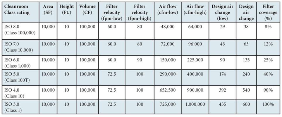
Table 2: Cleanroom recirculation air design analysis
Recirculation air handling units (RAHUs) are usually a lower cost option for a recirculation air system. They are typically located on a fan deck or perimeter of a cleanroom, which provides maintenance accessibility from non-clean space. Disadvantages of RAHUs include high noise levels — rarely below 70 dB(A) and higher energy usage. These large units also take up critical facility space, whether at the fan deck level or in an adjacent mechanical room, and fan deck RAHUs can raise the height of a building.
Vertical Laminar Flow (VLF) fan towers rely on laminar airflow to control particulate contamination through the vertical profile of the cleanroom. Laminar airflow refers to air moving at the same speed and in the same direction, with little or no cross-over air streams that can randomly deposit particles. Usually located on the perimeter of a cleanroom, VLF fan units fit in the same area required for sensible coils and a return chase, which allows for maintenance accessibility either from the subfloor beneath the cleanroom or from an adjacent chase. VLF fan units are usually a lower cost option for large, open ballroom cleanrooms with filter coverage greater than 50 percent. Used in conjunction with variable frequency drives (VFDs) equipped with large premium efficiency motors they have lower energy usage. While installing small, mini-VLF fan towers of around 12,000 cfm is relatively easy, large VLFs greater than 75,000 cfm are difficult to install. Like RAHUs, these systems can be noisy, with sound levels of 65 dB(A). VLF fan units also require a more costly and time-intensive gel ceiling grid and a positive pressure plenum can lead to particles or gel leaking into cleanroom space.
Filter fan units are located on top of the cleanroom ceiling grid in the plenum space, so these systems don’t take up facility floor space and offer maintenance access from below or above. These units offer quiet operation, with noise levels as low as 55 dB(A) or less easy to achieve. Units using the latest DC motor models offer high reliability, with mean time between failures approaching 10 years, and have very low energy usage. They have a negative pressure plenum that forces any leaks up into the plenum not into the cleanroom and a gasketed ceiling grid can be used. Filter fan units are easy to install and very cost competitive when coverage is less than 50 percent, but typically a high quantity of units is required for greater coverage or for large cleanrooms.
Cleanroom construction process
Building out a cleanroom and adjacent environments is a multi-stage construction process and particular protocols must be maintained at each stage of the construction to insure the integrity of the cleanroom. The stages are Stage 0 — Regular Construction; Stage 1 — Clean Construction; Stage 2 — Pre Cleanroom Construction; and, finally, Stage 3 — Active Cleanroom. Following are the important steps in each stage.
The regular construction phase is what must contractors are used to, but in the context of a cleanroom special attention should be paid to housekeeping to set the tone for cleanliness. At this stage there are no material restrictions and standard personal protective equipment, such as hard hats, safety glasses and vests, should be used. Take care to protect building materials as well. Construction workers should apply standard good housekeeping practices and complete daily and hourly clean-ups.
All drywall work should be complete if possible before the first stage of actual clean construction. During this phase, conduct daily and hourly cleanup using vacuums and start using a daily cleaning service. There should be no unnecessary trash or debris in cleanroom area and you should use multiple rugs as well as sticky mats to prevent dirt from entering. This is also when you begin to conduct particle counts.
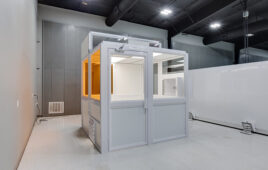
In the second stage, control and limit access to the cleanroom area and establish a smock room/air lock for entry/exit with an air cleaner. Workers must wear booties in the area and use sticky mats on floors. There should be no wood, cardboard, or paper allowed in the area. A HEPA vac is required for all cutting/drilling in the cleanroom and the air systems should be on, but not the FFUs.
The third stage, which is for punching and finishing details, is the most restrictive. It includes all the precautions of Stage Two, plus several additional steps. At this stage, access is limited and workers must be fully smocked, including wearing lab coat or coveralls, hair/beard nets, booties, and gloves, and they must use a designated smock room. In addition to operating the MUA system, recirculation air is continuously cleaning the air.
Meeting all the specific requirements for a cleanroom does increase construction costs, but this varies based on the type of cleanroom, with the tightest, most restrictive rooms costing the most. On average, the price range for cleanrooms ranges from $1,000 per square foot for a Class 1 room down to below $200 per square foot for a Class 100,000 room.
When constructing a cleanroom, it’s important to not be intimidated by the process. In the end, it’s still just construction. By following the plans and specs while adhering the guidelines for each phase the cleanroom construction can be executed successfully and with few problems. To facilitate the process, remember that preconstruction is extra important, so develop a detailed schedule early and manage procurement carefully. Clearly communicate the construction schedule to all parties to keep everyone on the same page. Be prepared to manage contingencies, things will change so be flexible and adaptable.
Constructing cleanrooms is challenging, requiring careful attention to specific details in both design and construction procedure. Using the accepted industry standards and the UM as blueprints, however, will facilitate the successful completion of a cleanroom. Working in partnership with the cleanroom operator on the specific design assures that the resulting room will meet the needs of end users and enable them to achieve a desired ROI from the operating space.
Matt Strong, PE, LEED AP, is President of C1S Group, a full-service professional engineering and construction firm based in Dallas. Matt has more than 26 years of experience in the design and installation of mechanical and electrical systems. www.c1sinc.com