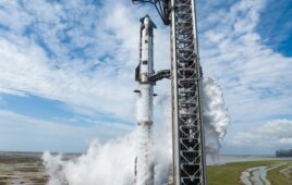
NASA’s X-59 aircraft, part of the Quesst mission, can reach supersonic speeds without causing a sonic boom. Development of the aircraft began in 2018, starting with risk reduction studies. The aircraft was built by Lockheed Martin Skunk Works in Palmdale, California, and completed its first flight on Oct. 28., 2025.
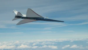
The X-59 aircraft. Credit: NASA / Lori Losey
The X-59 achieves its quiet supersonic flight by shaping the acoustic pressure wave. The airframe is designed to prevent shock waves from merging into a single boom, resulting in a gentle “sonic thump” that is minimally disruptive.
Supersonic flights are typically only done by military jets and are restricted to high altitudes and over oceans or uninhabited areas. Quiet supersonic flight could enable cargo and passenger flights at supersonic speeds over land.
Aerodynamic shaping
The X-59 has a unique, needle-like profile, the result of integrated 3D design, to reduce its noise when reaching sonic speeds. The aircraft’s nose takes up almost 30 feet of its 99.7 total feet in length. The nose is designed to shape and stagger the forward shock waves, preventing them from merging.
In addition to the nose design, the canards and stabilators are designed to break up the initial pressure rise, the sudden jump in air pressure that occurs as the forward shock waves of an aircraft reach an observer. This makes the pressure increase in smaller increments rather than one large jump, preventing the sonic boom.
The stabilator deflection and rounded bumps on the bottom of the vehicle gentle the slope of the pressure recovery, reducing noise. The pressure recovery is the return from under-pressure to ambient pressure, which causes the second bang of the sonic boom. By making this transition more gradual, the second bang is eliminated.
The high T-tail design minimizes the aft shock wave, which also contributes to the second bang in a sonic boom. The fuselage shape, wing platform camber and thickness of the craft were digitally optimized to manage the position and strength of shockwaves across the area on the ground where the sound is heard.
Engine and propulsion innovations
In most aircraft, the engine is located underneath or alongside the fuselage, allowing the shock waves produced by the engine and its air intake to travel directly toward the ground. In the X-59, the General Electric F414-GE-100 engine is mounted on top of the fuselage. This placement uses the body of the aircraft as a shield, reducing the number of shock waves.
Standard engine designs also experience inlet spillage, where air taken in by the engine adds to the aircraft’s sonic signature. X-59’s wings are designed to shield the ground from inlet spillage. The wings act as a physical shield to block the shove waves from the engine. The wings’ planform, camber and thickness were digitally optimized to manage the strength and position of the shock waves across the carpet, the area on the ground where the sound is felt.
The aft deck and nozzle were also engineered to manage the interaction between the engine’s exhaust plume and the shock waves from the tail surfaces. The engine uses hydraulics to control the throat and exit areas of the nozzle. This allows the aircraft to achieve different thrust conditions while maintaining the specific exhaust geometry needed for noise reduction.
The eXternal Vision System (XVS)
To maintain the ideal aerodynamic shape for noise reduction, the cockpit was set low and far back in the fuselage, which left no room for a forward-facing window. Instead, the XVS replaces the windscreen with a multi-camera, 4K-monitor system that provides the pilot with an augmented reality view of the flight path.
A series of forward-facing cameras located on the exterior of the aircraft capture the airspace in real-time. The XVS Pallet contains the computer processors, video distribution equipment, power distribution and network hardware.
The XVS hardware was tested on a Beechcraft King Air UC-12B. For comparative test flights, one pilot looked out a window while another only used the XVS.
Computational research and simulation
Researchers used advanced simulation workflows within the Launch, Ascent and Vehicle Aerodynamics (LAVA) computational framework to achieve a target ground volume of 75 dB.
They used Computational Fluid Dynamics (CFD) for the near-field, a high-order Space Marching (SM) method for mid-field propagation and the sBOOM solver for final ground signatures. By truncating the CFD domain to the domain of independence, the specific area where aerodynamic information affects the aircraft, researchers achieved a 50% reduction in computational costs.
A novel r-refinement method automatically redistributed grid points to resolve shock-dominated regions, such as the interactions between the engine plume and the shocks coming off of the tail.
The data was validated through supersonic wind tunnel experiments at NASA’s Ames and Glenn research centers. During the flight testing phase, NASA uses specialized airborne assets, such as an F-15D equipped with a Shock Sensing Probe, to measure the X-59’s acoustic signature in-flight.
The X-59 made its second flight on March 20, 2026, and continued test flights throughout April. Phase 2 of the mission, Acoustic Validation, is scheduled to begin in FY 2026, followed by Phase 3, Community Response Testing in FY 2027 through 2029.